
Temperature and humidity sensor
A simple power efficient temperature and humidity sensor that communicates using a 2.4 GHz radio. The device can run for almost a year on three AA batteries. The radio signal is received by a server (e.g. a Raspberry Pi) which acts as the hub in this system. The data received is stored in an sqlite database, and are visualized using matplotlib.
The primary purpose of the following article is to illustrate what advantages can be obtained by moving away from the Arduino platform. To keep the transition as straightforward as possible AVR microcontrollers are employed in all designs. Saving power, in order to run the system on battery for extended periods of time, moving from breadboards to perfboards to PCBs, and reducing the physical dimensions (i.e. size) will be discussed. Certainly, many more improvements in those areas could be made. Ultimately, the goal is to obtain a system that is cheap enough and small enough to put multiple sensors in every room and to have it run with minimal intervention.
Version 1: Breadboard prototype using Arduino
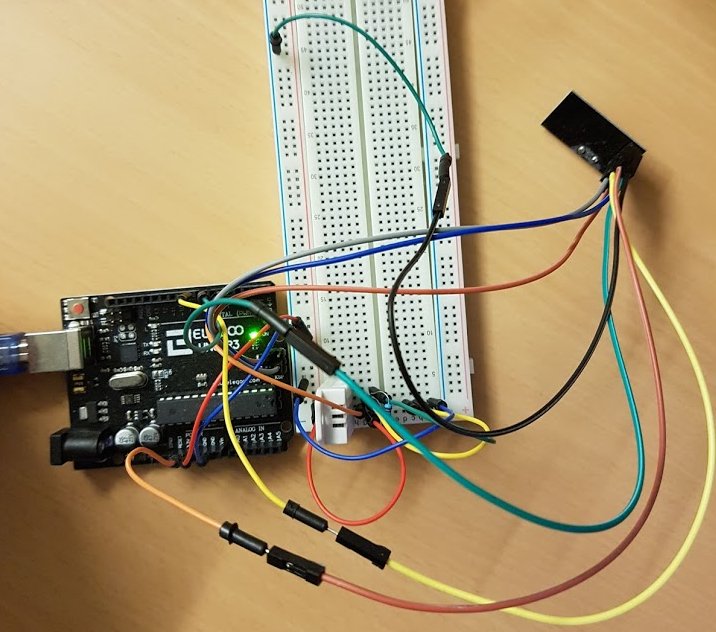
Setting up a temperature and humidity sensor with a radio on a breadboard is relatively straightforward. We use the Arduino RF24 library, to control the radio transmitter (nRF24L01+), and the Arduino DHT library to read data from the temperature and humidity sensor (DHT22).
Except for simplicity, there are no advantages to that design. Size and cost are obvious problems. But even more limiting is the power consumption. Even on relatively large capacity Li-ion USB battery packs this can barely be run for a day. One of the power draw is the always-on status LED, which is not easy to disable (putting a tape over the LED is certainly not going to help with power consumption). Also, the power efficiency of going from Li-ion to USB (at 5V) is not stellar, among other issues with the Arduino.
| Num. | Component |
|---|---|
| 1x | Arduino Uno |
| 1x | nRF24L01+ |
| 1x | DHT22/AM2302 |
| many | jumper wires |
The code that is run on the Arduino can be found here. Temperature and humidity are transmitted once per minute to the hub.
Version 2: Arduino
This is a minor modification that still uses the Arduino platform. The only improvement here is reducing the size. Instead of the breadboard and jumper wires we use a perfboard to solder the RF24 radio transceiver and the DHT22 temperature sensor on top. By using some pin headers we can directly plug the perfboard circuit into the Arduino, essentially an Arduino shield.
| Num. | Component |
|---|---|
| 1x | Arduino Uno |
| 1x | nRF24L01+ |
| 1x | DHT22/AM2302 |
| 1x | perfboard |
| pin headers |
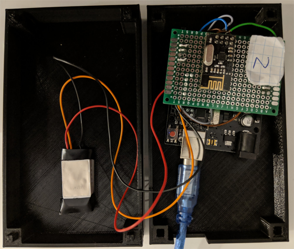
The case is made using an Anycubic I3 Mega 3d printer. There is an opening for the sensor on top which is fixed with adhesive tape. For fastening the two halves there is currently a very simple snap mechanism, which relies quite heavily on the characteristics of the 3d printer. This should be improved.
Version 3: ATMEGA328P
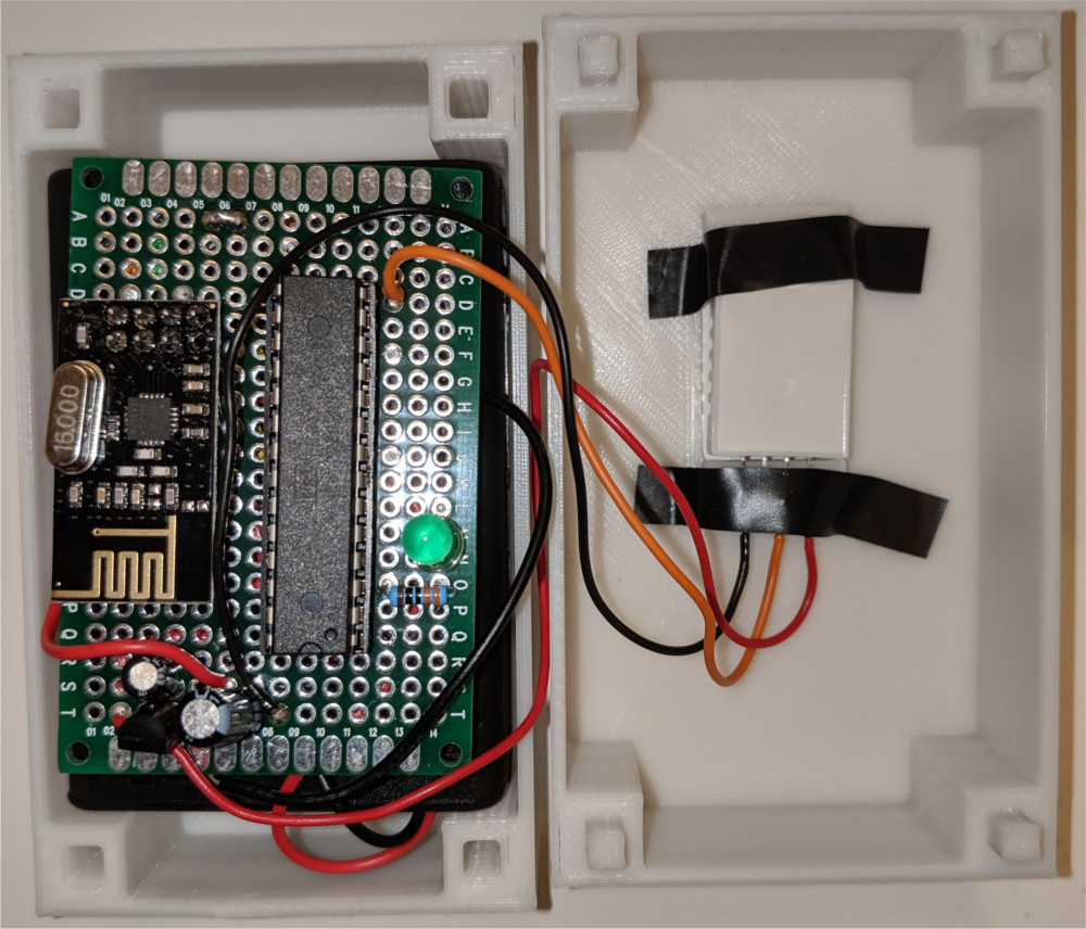
We now switch from the Arduino to using a microcontroller. This helps us across the board. Most strikingly in terms of battery life, but also a significant reduction in size and cost results. To keep this transition as straightforward as possible, we use the ATMEGA328P microcontroller from AVR (which is at the heart of the Arduino Uno).

The input voltage range of the ATMEGA328P is 1.8-5.5V, for the RF24 we have 1.9-3.6V, and for the DHT22 we have 3.3-5.5V. Thus, there is a common range of operation for all three components, namely 3.3-3.6V. The reader might assume that we can run all of these components on three (rechargeable) AA NiHM batteries. However, fully charged NiHM batteries typically have a voltage of approximately 1.4V. Thus, 3 batteries significantly exceed the tolerance of the RF24 module. For that reason, and to stabilize the battery power supply, we incorporate an LP2950 voltage regulator which reduces the voltage to 3.3V. The LP2950, even for relatively significant currents, can handle the relatively small input-output voltage differential mandated by the combined nominal voltage (3.6V) of the three NiHM batteries.
The AVR microcontroller fits easily, together with all the other components, on a 4x6cm perfboard. Thus, the size of the circuit is comparable to that of the three AA batteries.
| Num. | Component |
|---|---|
| 1x | ATMEGA328P |
| 1x | nRF24L01+ |
| 1x | DHT22/AM2302 |
| 1x | LP2950ACZ |
| 1x | LED |
| 1x | R (270 Ohm) |
| 3x | AA battery |
| 1x | 3xAA battery case |
| 1x | perfboard |
The code that runs on the AVR is compiled using gcc-avr. There is a good library for reading data from the DHT22. However, I could not get any of the libraries for the RF24 to work. Thus, I wrote some custom C code to send data using the RF24 radio.
Version 4: ATtiny44
The ATMEGA328P is a fairly large microcontroller (28 pins), which in some sense is overkill for what we need here. Thus, we switch to the ATtiny44 microcontroller (14 pins). This helps us save space on the perfboard. The ATtiny44 is also cheaper.
| # | Component |
|---|---|
| 1x | ATtiny44 |
| 1x | nRF24L01+ |
| 1x | DHT22/AM2302 |
| 1x | LP2950ACZ |
| 1x | LED |
| 1x | R (270 Ohm) |
| 3x | AA battery |
| 1x | 3xAA battery case |
| 1x | perfboard |

The main difference with the ATMEGA328P version is that the ATtiny44 does not have an onboard SPI controller. SPI is emulated on the ATtiny44 via USI and this requires that the MOSI and MISO connections are crossed over. That is, MISO on the RF24 radio is connected with MOSI on the microcontroller and vice versa. This is the opposite configuration compared to both the programmer and to the radio configuration on the ATMEGA328P. However, the actual code changes little.
Version 5: Power saving
Power consumption is drastically reduced by putting the microcontroller in a sleep state and only waking it up periodically (once every minute to read the sensor and transmit the corresponding data). The power draw of the microcontroller in this sleep state is extremely low.
However, in this configuration the LP2950 actually limits battery life due its (relatively) high quiescent current. Thus, we have replaced it by a MCP1702, which only consumes approximately 2 uA when the microcontroller is in its sleep mode. This version can run on three AA batteries for approximately a year.
Hub
All sensor data are communicated to a central hub. At my place, I can get reception from everywhere in the house if I place the hub at a central location. An Arduino with an nRF24L01+ is used to receive the signal which is then communicated via USB to a server and stored in an SQLite database. Python scripts are then used to periodically plot the data and serve them via http. The code for the hub can be found here.